+86 18513032986
How Does an Automatic Changeover Switch Work?
Admin 2026-05-25Content
- 1 The Short Answer: What an Automatic Changeover Switch Actually Does
- 2 The Core Components Inside an Automatic Changeover Switch
- 3 Step-by-Step: The Complete Operating Sequence
- 3.1 Phase 1 — Normal Operation (Utility Supply Active)
- 3.2 Phase 2 — Fault Detection and Time-Delay Confirmation
- 3.3 Phase 3 — Generator Start Signal
- 3.4 Phase 4 — Generator Stabilization Check
- 3.5 Phase 5 — Load Transfer to Generator
- 3.6 Phase 6 — Generator Run and Mains Recovery Monitoring
- 3.7 Phase 7 — Retransfer to Mains and Generator Cool-Down
- 4 Types of Automatic Changeover Switches and Their Applications
- 5 Key Parameters to Set When Commissioning an Automatic Changeover Switch
- 6 Wiring an Automatic Changeover Switch: What Actually Connects to What
- 7 Common Faults, Failure Modes, and How to Diagnose Them
- 8 Testing and Maintenance Schedules for Automatic Changeover Switches
- 9 Automatic Changeover Switch vs. Manual Changeover Switch: When Does Automation Pay Off?
- 10 Integration with Building Management Systems and Remote Monitoring
- 11 Sizing an Automatic Changeover Switch Correctly
The Short Answer: What an Automatic Changeover Switch Actually Does
An automatic changeover switch — also called an automatic transfer switch (ATS) — monitors the incoming mains supply continuously and, the moment it detects a failure or an out-of-tolerance voltage, it disconnects the load from the utility grid and reconnects it to a backup source such as a generator, inverter, or secondary supply. When the mains recovers, the switch reverses the process and hands control back to the grid, all without any manual intervention.
The entire transfer sequence — from sensing the fault to completing the changeover — typically takes between 0.5 seconds and 30 seconds, depending on the switch technology and how the system is configured. Open-transition switches break the connection to the old source before making the connection to the new one, while closed-transition switches briefly parallel both sources for a seamless, zero-interruption handoff.
Understanding how this mechanism works in detail is essential for anyone specifying, installing, or maintaining a backup power system, whether for a residential home, a commercial building, an industrial facility, or a critical data center.
The Core Components Inside an Automatic Changeover Switch
Before tracing the operating sequence step by step, it helps to know what physical and electronic parts make the switch work. Every ATS, regardless of brand or size, contains a small set of functional building blocks.
Voltage and Frequency Sensing Relay
This is the brain of the system. The sensing relay measures the mains voltage on all phases (or on a single phase for smaller units) typically several hundred times per second. It watches for voltage that drops below a preset threshold — commonly 85% of nominal — or rises above an upper limit, and it also monitors frequency deviation beyond ±2 Hz to 3 Hz. Some advanced units additionally check for phase sequence reversal and excessive harmonic distortion.
Switching Mechanism
The actual power path is controlled by one of three switching technologies:
- Contactor-based switches use two electromechanical contactors — one for the normal source, one for the emergency source — wired with an electrical and mechanical interlock to prevent both from closing simultaneously.
- Motorized circuit breaker switches use two molded-case or air circuit breakers driven by electric motors, offering better fault protection alongside the transfer function.
- Solid-state transfer switches (SSTS) use thyristors or IGBTs with no moving parts, capable of transferring in under four milliseconds — critical for sensitive electronics and data center loads.
Control Logic Board or PLC
Modern automatic changeover switches include a microprocessor-based control board or a small programmable logic controller. This module manages all time delays, communicates with the generator controller (via dry contacts or Modbus/CANopen protocols), logs events, and provides local or remote status indication. Entry-level residential units may use simpler relay-based logic, but commercial-grade switch panels almost always include a digital controller with an LCD display showing voltage, frequency, source status, and transfer counters.
Generator Start/Stop Output
A pair of dry-contact output terminals carries the start signal to the generator's automatic control panel. When the ATS detects a mains failure and the configurable delay (typically 3 to 10 seconds) expires, it closes this contact to crank the engine. After the generator stabilizes, the ATS receives a "generator ready" signal and then executes the transfer.
Manual Bypass Facility
Quality switch panels include a maintenance bypass that allows engineers to connect the load directly to either source and isolate the ATS mechanism for inspection or replacement, without ever de-energizing the building's distribution board. This feature is non-negotiable in hospitals, data centers, and water treatment plants.
Step-by-Step: The Complete Operating Sequence
Walking through each phase of a standard generator-backed ATS cycle makes the operating logic concrete and easy to follow during commissioning or fault-finding.
Phase 1 — Normal Operation (Utility Supply Active)
During normal operation the ATS holds the "Normal" contactor or breaker firmly closed, connecting all downstream loads to the utility grid. The "Emergency" contactor remains open, and the generator sits in standby mode — typically with its engine pre-heated by a jacket water heater set to around 30°C to 40°C so it can start reliably even in cold conditions. The sensing relay scans the incoming supply every few milliseconds but takes no action as long as voltage and frequency remain within their configured bands.
Phase 2 — Fault Detection and Time-Delay Confirmation
The moment mains voltage drops below the sensing threshold, the relay flags a fault. However, the ATS does not immediately start the generator. Instead, it starts a configurable transfer time delay — typically set between 2 seconds and 10 seconds for most commercial applications. This delay prevents nuisance starts caused by brief dips, micro-interruptions of a few cycles, or normal utility switching transients. If the mains recovers within this window, the counter resets and the generator never starts. Only if the fault persists through the full delay does the logic move to the next phase.
Phase 3 — Generator Start Signal
After confirming the outage, the ATS closes its start-output contacts and sends the crank signal to the generator's engine control module. The generator attempts to start — most modern units are configured for up to three start attempts of around 10 seconds each, with a brief rest between tries. A healthy diesel or gas generator running on a pre-heated engine will typically reach rated voltage and frequency within 8 to 15 seconds of receiving the start command.
Phase 4 — Generator Stabilization Check
Once the generator starts, the ATS sensing circuit monitors the emergency source terminals. It will not transfer the load until the generator output voltage is within ±10% of nominal and frequency is within ±3 Hz for a continuous period — often 3 to 5 seconds. This stabilization window ensures the generator's automatic voltage regulator (AVR) and governor have settled, preventing a transfer onto an unstable source that could trip sensitive equipment.
Phase 5 — Load Transfer to Generator
With the generator confirmed stable, the ATS executes the transfer. In an open-transition switch, the Normal contactor opens first, then after a dead time of approximately 100 milliseconds to 200 milliseconds the Emergency contactor closes. This brief interruption is intentional — it prevents out-of-phase paralleling between the decaying utility voltage and the generator. In a closed-transition switch, sophisticated synchronizing circuitry matches the phase angle, voltage magnitude, and frequency of both sources before momentarily paralleling them during the transfer, resulting in a make-before-break handover with no interruption at all.
Phase 6 — Generator Run and Mains Recovery Monitoring
The load now runs entirely on generator power. The ATS simultaneously monitors the utility supply terminals. When the utility voltage returns within tolerance and stays there for a programmable retransfer delay — typically 1 to 30 minutes — the logic confirms the grid has fully recovered and is stable. Long retransfer delays (10 to 30 minutes) are common in industrial and commercial applications to avoid repeatedly cycling between sources during intermittent grid disturbances.
Phase 7 — Retransfer to Mains and Generator Cool-Down
Once the retransfer delay expires, the ATS transfers the load back to the utility supply using the same open-transition or closed-transition process described above. The generator does not stop immediately. The ATS keeps the engine running unloaded for a cool-down period of 3 to 10 minutes — a vital step that allows exhaust manifolds, turbochargers, and cooling systems to reach safe temperatures before shutdown. Skipping this step drastically shortens turbocharger life and risks oil coking inside the bearing housing. After the cool-down timer expires, the ATS opens the generator start contacts and the engine shuts down, returning the system to Phase 1.
Types of Automatic Changeover Switches and Their Applications
Not all automatic changeover switches are built the same way or intended for the same job. The right choice depends on load type, acceptable interruption time, available budget, and installation constraints.
| Switch Type | Transfer Time | Typical Interruption | Best For |
|---|---|---|---|
| Contactor-based (open transition) | 2–30 sec (includes gen start) | Brief (100–300 ms after gen ready) | Residential, small commercial |
| Motorized breaker (open transition) | 10–40 sec | Brief (100–300 ms after gen ready) | Industrial, large commercial |
| Closed-transition ATS | 10–40 sec (includes synchronizing) | Zero (make-before-break) | Hospitals, data centers |
| Solid-state transfer switch (SSTS) | <4 ms | Sub-cycle (virtually zero) | Data centers, broadcast, pharma |
| Dual-source contactor (2-generator) | Varies by config | Brief to zero | Sites with two backup generators |
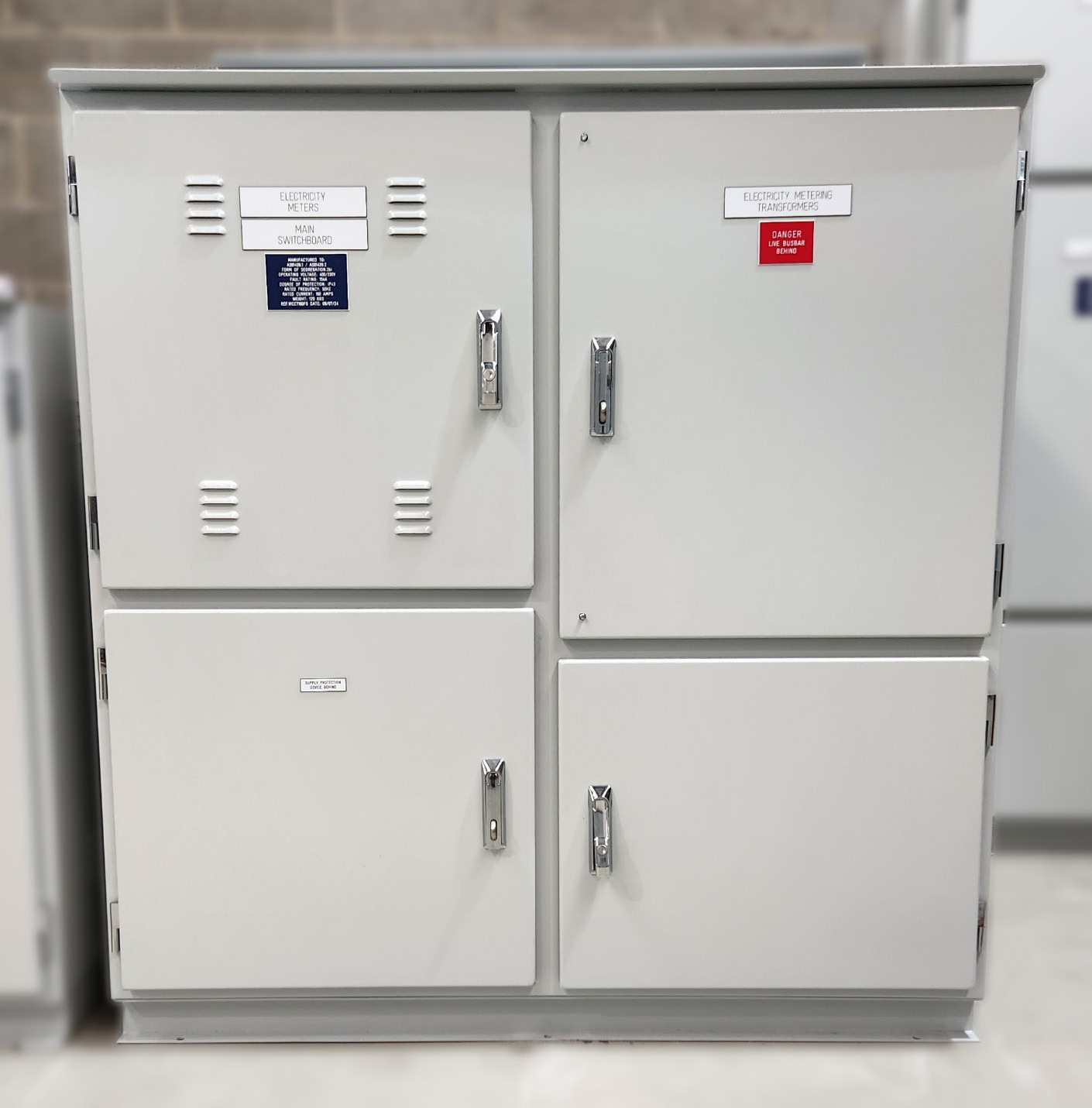
Residential and Small Commercial Switch Panels
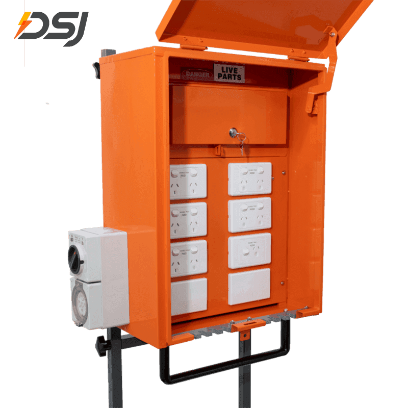
For homes and small offices, a compact ATS is typically integrated into or mounted alongside the main distribution board — also referred to as a switch panel in North America. These units range from 16 A to 125 A and may protect the entire premises or just selected essential circuits such as lighting, refrigeration, and security systems. Popular configurations use a 4-pole changeover to switch all four conductors (three phases plus neutral) in three-phase installations, or a 2-pole unit for single-phase supplies.
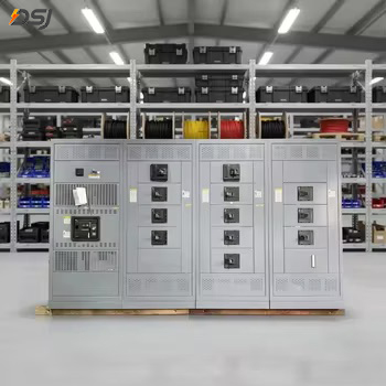
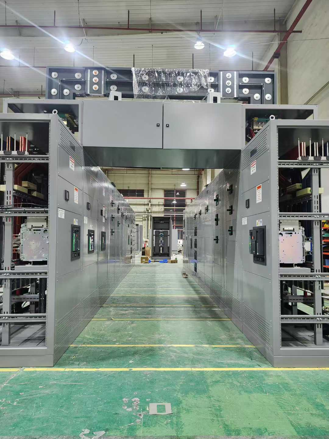
Commercial and Industrial Transfer Switch Panels
Large buildings, factories, and campuses use freestanding ATS switch panels rated from 160 A to 6,300 A or more. These enclosures often include the ATS mechanism, digital controller, current transformers for metering, space for surge protection devices, and bus bars connecting to multiple distribution circuits. In complex facilities, several ATS units may be deployed at different voltage levels — for instance, one at medium voltage (11 kV) to transfer the entire site, and secondary units at 400 V level for critical sub-loads like server rooms or operating theaters.
Inverter-Backed ATS for Solar and Battery Systems
Automatic changeover switches are not limited to generator backup. Modern battery energy storage systems and hybrid solar inverters use integrated ATS functionality to switch between grid, solar, and battery sources. Some hybrid inverters perform this changeover in under 20 milliseconds — fast enough that most computer power supplies and variable-speed drives do not even notice the transition. In off-grid systems, the ATS logic determines priority rules: solar first, battery second, grid or generator as a last resort.
Key Parameters to Set When Commissioning an Automatic Changeover Switch
Getting the time delays and threshold settings right at commissioning is just as important as choosing the correct hardware. Poorly set parameters are responsible for a large proportion of ATS failures in the field — including nuisance transfers, failed retransfers, and generator damage.
Under-Voltage Pickup and Dropout Thresholds
The dropout threshold is the voltage level at which the ATS decides the mains has failed. Setting it too high (for example, at 95% of nominal) will cause transfers during normal voltage fluctuations on a weak grid. Setting it too low (below 80%) risks running sensitive motors on damaging undervoltage before the transfer occurs. A common starting point is dropout at 85% and pickup at 90% of nominal, providing a hysteresis band that prevents chattering near the threshold.
Transfer Delay (Time to Start Generator)
This delay starts when a fault is first detected. For most applications, 3 to 5 seconds is enough to ride through brief dips. In areas with frequent short outages of 1 to 2 seconds, extending this to 10 to 15 seconds can dramatically reduce unnecessary generator starts — each of which adds hours to service intervals and fuel consumption. Conversely, in a data center or hospital setting where UPS batteries are limited, a transfer delay of 2 seconds or less may be required.
Retransfer Delay (Time to Return to Mains)
After the grid returns, waiting long enough before retransferring is critical in areas prone to intermittent outages. Returning to the grid 30 seconds after it recovers, only for it to fail again within minutes, wastes fuel and increases wear. Most engineers configure 10 to 30 minutes for industrial and commercial sites. Some programmable ATS controllers allow different retransfer delays based on the time of day or load profile.
Generator Cool-Down Timer
As noted above, 5 minutes is a minimum recommended cool-down period for turbocharged generators. Larger units above 500 kVA may need 8 to 10 minutes. The ATS keeps the start contacts energized (engine running) until this timer expires after the retransfer, then opens the contacts to shut the engine down.
Over-Voltage and Frequency Protection
While under-voltage gets most attention, over-voltage and frequency deviation are equally important. A generator with a failing AVR can produce 130% of nominal voltage in seconds, destroying equipment across the building. Setting an over-voltage trip at 110% of nominal with a 1-second delay, and a frequency trip at ±3 Hz from nominal, protects downstream equipment from a faulty backup source — something a basic ATS without these features cannot do.
Wiring an Automatic Changeover Switch: What Actually Connects to What
The wiring of an ATS follows a consistent logical pattern regardless of the specific brand or current rating, though the physical layout of terminals varies between manufacturers.
Power Circuit Connections
The ATS has three sets of power terminals. The Normal (N) input terminals connect to the incoming utility supply, typically arriving from the main isolator or the utility meter. The Emergency (E) input terminals connect to the generator output or inverter output. The Load (L) output terminals connect to the downstream distribution board or switch panel that feeds the protected circuits. It is critically important that the utility neutral and generator neutral are properly bonded — many ATS-related problems come from incorrect neutral switching, especially when the generator has a floating neutral that must be bonded to earth only when the ATS connects it to the load.
Control Wiring to the Generator
Two pairs of control wires run between the ATS and the generator's control panel. The first pair carries the start/stop signal as a dry contact closure — typically a two-wire connection to the remote start terminals on the generator's AMF (Automatic Mains Failure) controller. The second pair brings back a "generator ready" or "bus healthy" signal from the generator to the ATS, confirming the output has stabilized. Some installations add a third pair for a generator fault alarm output, which the ATS can use to illuminate a panel indicator or trigger a building management system alarm.
Earthing and Bonding Considerations
Correct earthing is one of the most misunderstood aspects of ATS installation. In a TN-S or TN-C-S earthing system, the installation earth is derived from the utility supply. When the ATS switches to a generator that has its own isolated neutral, the earth reference must follow the neutral. This is why 4-pole ATS units (switching all three phases plus the neutral) are required in many installations — they ensure the load's neutral always follows its source, preventing dangerous neutral displacement voltages.
Common Faults, Failure Modes, and How to Diagnose Them
Automatic changeover switches are generally reliable, but they do fail — and when they do, the consequences can range from an unnecessary generator start to a complete failure to transfer during a real outage. Knowing the common failure modes speeds up diagnosis considerably.
Failure to Transfer on Mains Loss
This is the most serious failure mode. Root causes include:
- Failed sensing relay that no longer detects the undervoltage condition.
- Open-circuit or corroded control wiring to the generator, preventing the start signal from reaching the engine controller.
- Generator fails to start (flat battery, stale fuel, faulty fuel solenoid) so the ATS never receives a "generator ready" signal and holds the load on the dead mains.
- Mechanical interlock jammed due to corrosion or a previous overcurrent event that partially welded a contactor.
Nuisance Transfers (Transfers Without a Real Outage)
If the ATS transfers during every brief voltage dip rather than waiting out the fluctuation, the transfer delay is set too short, or the sensing threshold is too high. Nuisance transfers are disruptive and add unnecessary engine starts. Increasing the transfer delay from 2 seconds to 5 to 10 seconds solves most cases. If the problem persists, suspect a noisy or failing sensing relay picking up spurious signals from harmonic-heavy loads.
Failure to Retransfer to Mains
If the ATS stays on generator power even after the utility recovers, check whether the mains voltage sensing on the Normal input terminals is functioning — a blown fuse on the sensing circuit is a surprisingly common cause. Also verify that the retransfer threshold (pickup voltage) is not set higher than the actual recovered utility voltage, which can happen if the grid is supplying low voltage after a fault restoration.
Both Sources Showing as "Available" Simultaneously
This indicates a wiring error or a failed interlock. In an open-transition ATS, this condition should be physically impossible due to the mechanical interlock, but if both status LEDs light up simultaneously, suspect a faulty sensing input that is reading residual voltage from the load side rather than the source side. This can happen if the control transformer is powered from the load bus rather than individually from each source.
Testing and Maintenance Schedules for Automatic Changeover Switches
An ATS that is never tested is a liability. Many organizations discover during a real power cut that their changeover switch has been silently broken for months or years. A structured maintenance program prevents this.
Weekly Automatic Exercise Run
Most modern ATS controllers include a built-in exercise scheduler. Setting it to start the generator and run it unloaded for 20 to 30 minutes once a week circulates oil, charges the battery, burns off moisture, and exercises the cooling system. Some operators configure a loaded exercise — the ATS actually transfers the building load to the generator — once a month during a low-risk period such as a weekend night, which provides a more realistic validation.
Annual Full-Function Test
Once a year, simulate a real mains failure by manually opening the utility incomer while the generator is in standby. Verify and document the transfer time, the load voltage on generator, the cool-down behavior, and the retransfer after restoring the utility. Check all terminal connections for tightness — thermal cycling causes copper connections to loosen over time, and a loose terminal carrying 400 A can reach temperatures above 200°C within minutes under load, causing insulation damage and fire risk. Inspect contactor contacts for erosion, and exercise the manual bypass handle through its full range to ensure it moves freely.
Contact and Insulation Testing
Every three to five years, conduct insulation resistance testing on the power cables entering and leaving the ATS, and measure contact resistance across each set of power contacts using a micro-ohmmeter. Contact resistance above 50 to 100 microohms on a new contactor-type ATS typically indicates contact erosion or contamination and warrants replacement of the contactor assembly.
Automatic Changeover Switch vs. Manual Changeover Switch: When Does Automation Pay Off?
Manual changeover switches are still used in situations where outages are rare, an operator is always on site, or the load is not critical enough to justify ATS cost. A manual switch panel is mechanically simpler, has no electronics to fail, and costs significantly less — a quality manual 125 A 4-pole changeover switch might cost a fraction of an equivalent ATS unit.
However, the case for automation is compelling in most real-world scenarios:
- Response speed: A manual switch requires a person to notice the outage, walk to the switch panel, start the generator, wait for it to stabilize, and operate the changeover — a process that takes 5 to 15 minutes at best. An ATS completes the same process in under 30 seconds.
- Unmanned sites: Telecom base stations, pumping stations, remote data nodes, and holiday properties cannot rely on someone being present to operate a manual switch.
- Night-time and weekend outages: The majority of grid faults occur during storms, often at night. Expecting staff to respond manually at 2 AM is unrealistic for most organizations.
- Regulatory requirements: Hospitals, care homes, fire safety systems, and emergency lighting in commercial buildings are legally required in many jurisdictions to have automatic changeover, not manual.
In nearly every setting where a backup generator is installed, an automatic changeover switch rather than a manual one is the correct technical and practical choice — the additional cost is modest relative to the total generator installation cost, and the reliability benefit is substantial.
Integration with Building Management Systems and Remote Monitoring
Modern automatic changeover switches are increasingly expected to do more than simply switch power. Digital communication capabilities allow the ATS to become an active node in a building's energy and safety management infrastructure.
Communication Protocols
Most commercial-grade ATS controllers now include one or more of the following interfaces:
- Modbus RTU (RS-485) — the most common industrial protocol, allowing the BMS to read transfer status, source voltages, transfer counts, and fault codes.
- Modbus TCP (Ethernet) — the same data over a standard Ethernet port, simplifying integration into IP-based building management platforms.
- BACnet/IP — preferred in HVAC and building automation environments.
- Dry contact outputs — simple volt-free contacts indicating "on generator", "mains failed", "ATS fault", and "generator fault", which can connect to any BMS input card regardless of protocol.
Remote Test and Override Capabilities
Network-connected ATS units allow facility managers to initiate a test transfer from a web browser or smartphone app without visiting the switch panel room. Alarm notifications can be pushed via email or SMS the moment a transfer occurs or a fault is detected, enabling rapid response even from off-site. Event logs storing the last 500 to 1,000 transfer events with timestamps, source voltages at the time of transfer, and transfer duration provide valuable data for maintenance planning and incident reports.
Sizing an Automatic Changeover Switch Correctly
Selecting the correct current rating for an ATS is not simply a matter of matching it to the generator's output. The switch must handle the full connected load, including starting currents from motors, which can reach six to eight times the full-load running current for a fraction of a second during each motor start.
Utilization Category
ATS contactors and breakers are rated for specific IEC utilization categories. For resistive and lighting loads, AC-1 rating is sufficient. For motor loads, AC-3 or AC-4 rating is required, as these contacts must interrupt motor inrush currents without welding. Always verify that the ATS is rated for the actual load type, not just the load current — an AC-1-rated contactor used on a motor-heavy load will fail prematurely.
Service Factor and Derating
As a general rule, size the ATS at 125% of the maximum connected load current to allow for load growth and to keep contacts operating well within their thermal limits. In high-ambient-temperature environments above 40°C — common in tropical climates or poorly ventilated plant rooms — apply the manufacturer's derating curves, which typically reduce contact ratings by 1% to 2% per degree Celsius above the reference temperature.
Short-Circuit Current Rating (SCCR)
Every ATS must be rated for the prospective short-circuit current at its installation point. Installing an ATS with an SCCR of 10 kA at a bus bar where the prospective fault current is 25 kA is a serious safety hazard. The upstream overcurrent device (fuse or breaker) must be coordinated with the ATS to limit let-through current within the ATS's withstand rating, and this must be verified using the manufacturer's coordination tables — not assumed.
For exclusive deals and latest offers, sign up by entering your email address below.


Copyright © DSJ Electrical Co., Ltd. All Rights Reserved
Power Distribution Equipment & System Manufacturer