+86 18513032986
What Are the Main Components of a Circuit Breaker?
Admin 2026-04-13Content
- 1 The Five Main Components of a Circuit Breaker
- 2 The Frame: Structural Foundation and Electrical Insulation
- 3 The Operating Mechanism: Speed and Reliability in One Assembly
- 4 The Contacts: Where the Circuit Is Made and Broken
- 5 The Arc Extinguisher: Controlling the Inevitable Spark
- 6 The Trip Unit: Detecting Faults and Initiating Protection
- 7 How the Five Components Work Together During a Fault
- 8 Component Summary: What Each Part Does at a Glance
- 9 Additional Components in Specific Circuit Breaker Types
- 10 Why Component Knowledge Matters for Selection and Maintenance
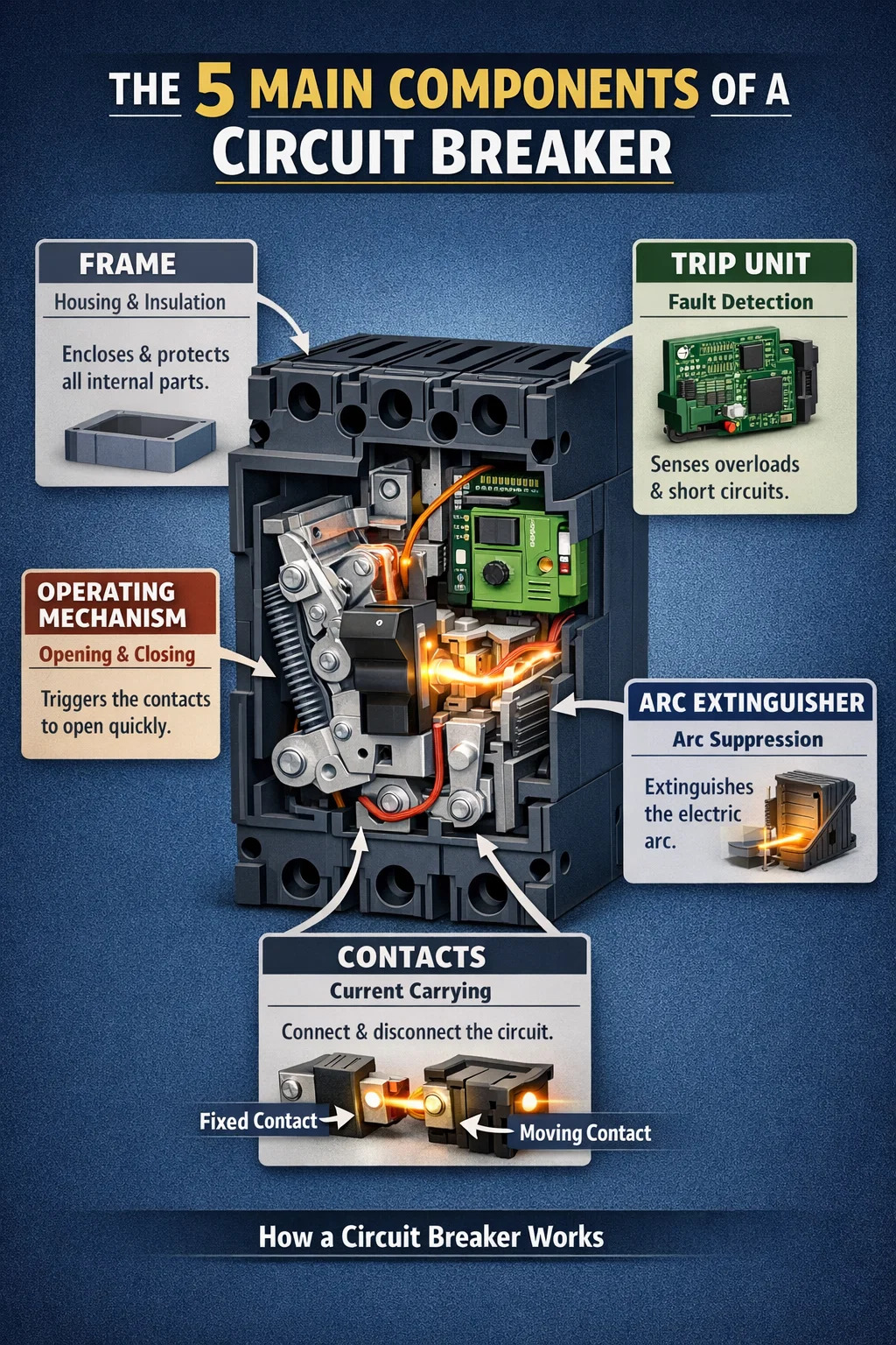
The Five Main Components of a Circuit Breaker
A circuit breaker has five universal components: the frame, operating mechanism, contacts, arc extinguisher, and trip unit. These five parts appear in virtually every type of circuit breaker — from the miniature circuit breaker (MCB) protecting a single household outlet to large molded case circuit breakers (MCCBs) rated up to 2,000 amps in industrial facilities. Understanding what each component does helps electricians, engineers, and facility managers select the right breaker, diagnose failures faster, and maintain electrical systems more effectively.
The basic job of a circuit breaker is straightforward: detect a fault, then interrupt the flow of current before that fault causes a fire, destroys insulation, or damages equipment. The five components divide this job among themselves — the frame contains everything, the trip unit detects the problem, the operating mechanism responds, the contacts physically break the circuit, and the arc extinguisher cleans up the dangerous spark that follows. Each component is critical. Remove or compromise any one of them, and the entire protective function of the breaker collapses.
The Frame: Structural Foundation and Electrical Insulation
The frame is the outer housing of the circuit breaker. It does two jobs simultaneously: it provides the mechanical strength needed to withstand the violent forces generated during a fault interruption, and it provides electrical insulation to keep current safely contained inside the device.
Frames come in two primary materials. Molded case frames are made from glass-polyester or thermoset composite resins — plastics engineered specifically for high dielectric strength and resistance to heat. These are used in miniature circuit breakers (MCBs), insulated case circuit breakers, and most molded case circuit breakers (MCCBs) found in residential and light commercial panels. Metal frames, by contrast, are bolted and welded from precision steel or aluminum components. These appear in low-voltage power circuit breakers and medium-voltage vacuum breakers where higher mechanical ratings are required.
The frame size directly determines the current rating the breaker can safely handle. Larger frames accommodate more robust internal components and are used for higher amperages — sometimes reaching up to 6,300 amps in heavy industrial applications. The frame also shields internal parts from dust, moisture, and accidental contact, which is why the ingress protection (IP) rating of a circuit breaker is largely determined by how well the frame is sealed.
During a fault, the energy released inside the breaker is enormous. Pressure waves, heat, and mechanical shock all act on the frame in milliseconds. A well-designed frame absorbs and contains these forces rather than allowing them to fracture the housing and create external hazards. This is why circuit breaker frames undergo rigorous short-circuit withstand tests as part of certification to standards like IEC 60947-2 or UL 489.
The Operating Mechanism: Speed and Reliability in One Assembly
The operating mechanism is the mechanical heart of the circuit breaker. Its function is to open and close the contacts — either manually when an operator flips the handle, or automatically when the trip unit signals a fault. The defining characteristic of a good operating mechanism is speed. A breaker that opens slowly allows fault current to flow longer, increasing the risk of arc flash, conductor damage, and equipment destruction.
Modern circuit breakers use a quick-make, quick-break toggle design. This means the speed at which the contacts snap open or closed is entirely independent of how fast the operator moves the handle. Whether a person flips the switch slowly or quickly, the internal spring mechanism releases at the same speed. This prevents the contacts from "resting" at an intermediate position where arcing would be prolonged and damaging.
Types of Operating Mechanisms
- Over-toggle mechanism: Used in most miniature and molded case circuit breakers. A spring stores energy during closing and releases it instantly during tripping.
- Two-step stored energy mechanism: Found in larger power circuit breakers. Energy is stored separately (manually or by a motor) before the breaker is closed or opened, enabling faster and more reliable operation independent of operator input.
- Thermal mechanism: Uses a bimetallic strip that bends when heated by excess current, mechanically tripping the breaker. Common in smaller MCBs for overload protection.
- Magnetic (solenoid) mechanism: Uses the magnetic field generated by a short-circuit current to rapidly pull a plunger that trips the breaker. Response times can be as fast as a few milliseconds.
- Hydraulic-magnetic mechanism: Uses a coil surrounding a fluid-filled tube. The fluid slows the magnetic plunger at lower currents (providing a time delay) but allows fast response at high fault currents. This type is temperature-independent, making it suitable for marine and aerospace applications.
Most circuit breakers also feature a "free trip" or "positive trip" design — meaning the breaker will still open even if someone holds the handle in the "on" position. This is a safety-critical feature. Without it, a person could inadvertently prevent the breaker from protecting a faulty circuit simply by gripping the panel handle.
The Contacts: Where the Circuit Is Made and Broken
The contacts are the conductive elements inside the circuit breaker that physically carry current when closed and physically separate to interrupt it when the breaker trips. Every circuit breaker has at least one set of fixed contacts and one set of moving contacts. When the breaker is in the "on" position, the moving contacts press against the fixed contacts, completing the electrical path. When a trip occurs, the operating mechanism drives the moving contacts away from the fixed contacts, opening the circuit.
Contact material matters significantly. Most contacts are made from silver-based alloys — silver cadmium oxide, silver tin oxide, or silver tungsten — chosen for their combination of high electrical conductivity, resistance to welding (contacts sticking together under high fault current), and resistance to arc erosion. In high-voltage or high-current applications, contacts may be made from copper-chromium or tungsten-copper composites.
Contacts wear over time. Arc erosion — the gradual burning away of contact material each time an arc forms during opening — is the primary cause of contact degradation in circuit breakers. For this reason, air circuit breakers (ACBs) used in large industrial facilities are designed with replaceable contacts, allowing maintenance teams to restore the breaker to original specification without replacing the entire unit. Molded case and miniature circuit breakers, however, are generally considered non-maintainable and are replaced as a unit when contacts degrade beyond acceptable limits.
Fixed vs. Moving Contacts
The fixed contact is stationary and connected to the incoming supply terminal. The moving contact is attached to the operating mechanism and connected to the load terminal. When the breaker opens, the moving contact separates from the fixed contact. The gap between them must be large enough to withstand the voltage that appears across the open contacts without re-striking an arc — a distance that increases with rated voltage. In a 240V residential breaker, this gap may be just a few millimeters; in a medium-voltage breaker rated at 15 kV, the gap is substantially larger.
The Arc Extinguisher: Controlling the Inevitable Spark
When the contacts of a circuit breaker separate under load, an electrical arc forms across the gap. This is unavoidable — the arc is sustained by the ionized gas between the contacts and by the energy still being fed from the supply. Without an arc extinguisher, this arc would continue to flow current even after the contacts are physically separated, defeating the purpose of opening the breaker. Worse, a sustained arc generates temperatures exceeding 6,000°C and can destroy the contacts, ignite the housing, or cause a catastrophic arc flash incident.
The arc extinguisher — also called the arc chute or arc quenching chamber — is designed to rapidly extinguish the arc by cooling it, lengthening it, and splitting it into smaller sections that self-extinguish. The specific method used depends on the type and rating of the circuit breaker.
Six Arc Extinguishing Methods Used in the Industry
- Arc chute with splitter plates: The most common method in MCBs and MCCBs. Parallel steel plates divide the arc into a series of shorter arcs, each of which extinguishes more easily. The arc voltage across the series of sub-arcs quickly exceeds the supply voltage, forcing the arc to extinction.
- Vacuum: Used in medium-voltage circuit breakers. The contacts operate inside a sealed vacuum bottle. In a vacuum, there are no gas molecules to sustain the arc, so it extinguishes almost instantly at the first natural current zero. Vacuum circuit breakers are now the dominant technology for voltages from about 1 kV to 40.5 kV.
- SF₆ (sulfur hexafluoride) gas: Used in high-voltage breakers above 72 kV. SF₆ has exceptional arc-quenching properties due to its high dielectric strength and electronegative nature. However, SF₆ is a potent greenhouse gas with a global warming potential roughly 23,500 times that of CO₂, and there is significant regulatory pressure in the EU and elsewhere to phase it out in favor of alternative gases.
- Air blast: High-pressure air is directed across the arc, cooling and stretching it until extinction. Used in older large switchgear installations, now largely superseded by vacuum and SF₆ technology.
- Oil immersion: The contacts operate submerged in insulating oil. The arc vaporizes the oil, creating a gas bubble that helps extinguish the arc. Oil circuit breakers were common throughout the 20th century but are now considered obsolete for new installations due to fire risk and maintenance requirements.
- Magnetic blowout: A magnetic field deflects and lengthens the arc, cooling it and assisting extinction. Used in DC circuit breakers and some specialty AC applications where the natural current zero crossing — which aids AC arc extinction — is absent.
The arc extinguisher is arguably the most technically demanding component in a circuit breaker to design correctly. A breaker's interrupting rating — the maximum fault current it can safely clear — is largely determined by the effectiveness of its arc extinguishing system. Exceeding this rating can result in the arc burning through the housing and causing an arc flash explosion.
The Trip Unit: Detecting Faults and Initiating Protection
The trip unit is the intelligence of the circuit breaker. Its job is to continuously monitor the current flowing through the circuit, detect when that current exceeds safe limits, and then signal the operating mechanism to open the contacts. Without an accurate and reliable trip unit, the breaker cannot fulfill its protective function.
There are two fundamental types of abnormal current conditions that trip units must respond to, and they require different responses:
- Overload: A current above the rated value but below the short-circuit level. An overload may be 125% or 150% of rated current. At these levels, conductors and equipment overheat gradually. The trip unit is designed to allow a brief overload (to permit motor starting surges, for example) but trip after a sustained overload. The trip time is inversely proportional to the overcurrent magnitude — the larger the overload, the faster the trip.
- Short circuit: A near-instantaneous massive overcurrent, potentially hundreds or thousands of times the rated current. A short circuit must be cleared in milliseconds to prevent catastrophic damage. Trip units respond to this with an instantaneous (or nearly instantaneous) magnetic trip element.
Thermal-Magnetic Trip Units
The thermal-magnetic trip unit is the standard in most MCBs and smaller MCCBs. It combines two detection elements in one assembly. A bimetallic strip responds to sustained overloads: excess current heats the strip, causing it to bend and mechanically unlatch the operating mechanism. The time it takes to trip depends on how much the current exceeds the rated value — a 20% overload might take several minutes; a 200% overload might trip in a few seconds. A solenoid (electromagnet) provides instantaneous trip response to short circuits. When fault current reaches the magnetic trip threshold — typically 3 to 10 times the rated current depending on the breaker's trip curve — the solenoid plunger fires almost instantly, driving the operating mechanism open in under 10 milliseconds.
Electronic (Solid-State) Trip Units
Larger MCCBs, insulated case circuit breakers (ICCBs), and low-voltage power circuit breakers (LVPCBs) often use electronic trip units. These use current transformers to measure current in each phase and pass the signal to a microprocessor that applies programmable trip curves. Electronic trip units offer several advantages over thermal-magnetic designs:
- Adjustable long-time pickup (overload threshold) and delay settings
- Adjustable short-time pickup and delay for coordination with downstream devices
- Instantaneous override that cannot be turned off (direct short circuit protection)
- Ground fault protection (sensing residual current to detect phase-to-ground faults)
- Real-time metering of voltage, current, power, and energy
- Communication interfaces (Modbus, Ethernet) for integration with building management systems
The programmability of electronic trip units is critical in industrial distribution systems where selective coordination is required. Selective coordination means that during a fault, only the breaker closest to the fault trips, while upstream breakers remain closed. This prevents a single fault from blacking out an entire facility. Achieving proper coordination requires carefully matched trip curves across all breakers in a distribution hierarchy — something that is far more achievable with adjustable electronic units than with fixed thermal-magnetic designs.
How the Five Components Work Together During a Fault
Understanding each component individually is useful, but seeing how they interact during an actual fault event reveals why circuit breaker design is a precise engineering discipline rather than a simple mechanical exercise.
When a short circuit occurs on a downstream circuit, fault current begins to rise extremely rapidly — in a 240V residential system, this can be thousands of amps within a fraction of a cycle. The trip unit detects this current surge through its magnetic element and fires almost instantly. The signal releases the latch in the operating mechanism, which drives the spring-loaded moving contacts away from the fixed contacts with maximum speed. As the contacts separate, the high current immediately forms an arc across the gap. The arc extinguisher drives this arc into the chute plates, lengthens and cools it, and extinguishes it within the first few milliseconds. The frame contains the entire event — the pressure, the heat, the ionized gases — and presents an intact housing to the outside world throughout.
This entire sequence — detection, mechanism release, contact separation, arc extinction — can occur in as little as 8 to 16 milliseconds in a modern current-limiting circuit breaker. That is less than one AC cycle at 60 Hz. The faster this sequence happens, the less energy the fault releases, and the less damage it causes to the protected circuit.
Component Summary: What Each Part Does at a Glance
| Component | Primary Function | Common Materials / Technologies | Failure Impact if Defective |
|---|---|---|---|
| Frame | Housing, insulation, mechanical strength | Thermoset resin, glass-polyester, steel | Arc flash external exposure, shock hazard |
| Operating Mechanism | Opens/closes contacts on command or trip signal | Spring toggle, stored energy, thermal, magnetic | Breaker fails to open; fault current not cleared |
| Contacts | Carry current when closed; interrupt when open | Silver alloys, copper-chromium, tungsten-copper | Overheating, welding, failure to interrupt |
| Arc Extinguisher | Extinguishes arc when contacts open | Steel splitter plates, vacuum, SF₆, oil | Arc flash, breaker destruction, fire |
| Trip Unit | Detects overload/short circuit; triggers trip | Bimetallic strip, solenoid, electronic relay | No protection; fault causes fire or equipment damage |
Additional Components in Specific Circuit Breaker Types
Beyond the five core components, certain types of circuit breakers include additional elements that extend their functionality. These are not universal but are important to understand when selecting or specifying a breaker for a particular application.
Shunt Trip Coil
A shunt trip unit is an add-on solenoid designed to open the breaker when energized by an external signal — typically a 24V DC or line voltage AC command. This allows the circuit breaker to be tripped remotely by a fire alarm system, emergency stop circuit, BMS command, or undervoltage relay. The shunt trip is a safety-critical addition in buildings where emergency disconnection of power is required during hazardous events. It does not replace the trip unit; it supplements it with a remote-tripping capability.
Ground Fault Circuit Interrupter (GFCI) Module
GFCI circuit breakers continuously compare the current in the hot wire against the current in the neutral wire. In a healthy circuit, these currents are equal. A difference as small as 4 to 6 milliamps — indicating that current is finding an unintended path to ground, potentially through a person's body — causes the GFCI module to trip the breaker within 1/40th of a second. This level of sensitivity is far beyond what the thermal-magnetic trip unit can detect, as that unit responds only to amperages in the range of the circuit's rated current. GFCI breakers are required by the NEC (National Electrical Code) in bathrooms, kitchens, outdoor receptacles, garages, and other locations where water and electricity may interact.
Arc Fault Circuit Interrupter (AFCI) Module
AFCI breakers detect the high-frequency current signatures produced by arcing faults — loose connections, damaged wiring insulation, or cords pinched under furniture — that would not trip a standard circuit breaker but are a leading cause of residential electrical fires. The AFCI module uses digital signal processing to distinguish between the normal arcing that occurs when a light switch is flipped and the sustained, dangerous arcing of a wiring fault. AFCI protection is now required by the NEC in bedrooms, living rooms, and most other dwelling areas.
Auxiliaries, Alarms, and Communication Modules
Larger circuit breakers used in commercial and industrial distribution systems are frequently equipped with auxiliary contacts (which signal the breaker's open/closed status to a control system), alarm contacts (which signal a trip condition), and communication modules (Modbus RTU, Modbus TCP, PROFIBUS, or Ethernet/IP) that allow the breaker's status, measured values, and trip log to be read remotely. These accessories transform the circuit breaker from a passive safety device into an active node in an intelligent power management network.
Why Component Knowledge Matters for Selection and Maintenance
Knowing the components of a circuit breaker is not purely academic. It has direct, practical implications for selecting the right breaker for an application, maintaining breakers in service, and troubleshooting failures.
Selection: Matching Components to Application Requirements
When specifying a circuit breaker, each component type determines a key rating or capability. The frame determines the maximum current rating. The arc extinguishing technology determines the interrupting capacity (the maximum fault current the breaker can safely clear — a breaker used in a fault level beyond its interrupting capacity can explode rather than interrupt). The trip unit type determines whether adjustability and communication are available. Choosing a breaker without understanding which components deliver which performance parameters leads to undersized or over-specified breakers — both costly mistakes.
Maintenance: What to Inspect and How Often
Industry standards such as NFPA 70B and NETA recommend periodic maintenance for circuit breakers. The inspection targets specific components:
- Contacts: Check for pitting, erosion, and discoloration (signs of arcing damage). Measure contact resistance with a low-resistance ohmmeter. Values significantly higher than the manufacturer's specification indicate worn contacts.
- Operating mechanism: Exercise the breaker through several open-close cycles to verify smooth operation and absence of sluggish movement. Lubricate pivot points per manufacturer recommendations — but never lubricate contact surfaces.
- Trip unit: Perform primary or secondary injection testing to verify that the trip unit responds within its published time-current curve tolerances. Electronic trip units may also have built-in self-test functions.
- Frame and arc chute: Inspect for carbon deposits, cracking, and physical damage. Clean carbon tracks that could provide a conductive path across insulating surfaces.
A circuit breaker that has not been tested or exercised for many years may fail to trip when needed — or may trip at the wrong time. The components that are most likely to degrade in dormant breakers are the trip unit (whose bimetallic strips may shift calibration) and the operating mechanism (whose lubrication may dry and stiffen). Breakers that protect critical loads should be tested at intervals not exceeding three to five years according to most electrical maintenance standards.
For exclusive deals and latest offers, sign up by entering your email address below.


Copyright © DSJ Electrical Co., Ltd. All Rights Reserved
Power Distribution Equipment & System Manufacturer