+86 18513032986


How does a dry type transformer work?
Admin 2026-03-13Content
- 1 The Core Operating Principle
- 2 Key Components and Their Roles
- 3 Thermal Management: How Heat Is Controlled
- 4 Voltage Regulation and Tap Changers
- 5 Efficiency and Losses
- 6 Dry Type vs. Oil-Filled Transformers: A Practical Comparison
- 7 Typical Applications
- 8 Monitoring and Protection
- 9 Maintenance Considerations
A dry type transformer works by transferring electrical energy between circuits through electromagnetic induction, using air or solid insulation materials instead of liquid coolants. Unlike oil-filled transformers, dry type units rely on cast resin, vacuum pressure impregnation (VPI), or open-wound coils with class F or H insulation systems to manage heat and withstand electrical stress. They are widely used in indoor, commercial, and industrial environments where fire safety, environmental protection, and low maintenance are priorities.
The Core Operating Principle
At its heart, a dry type transformer operates on Faraday's Law of Electromagnetic Induction. When alternating current (AC) flows through the primary winding, it generates a changing magnetic flux in the iron core. This flux links to the secondary winding, inducing a voltage proportional to the turns ratio between the two windings.
The voltage transformation ratio is expressed as:
V1 / V2 = N1 / N2
Where V1 and V2 are primary and secondary voltages, and N1 and N2 are the number of turns in each winding. For example, a transformer with a 10:1 turns ratio steps down 10,000V to 1,000V. Because no conducting current passes directly between the two windings, the circuits are electrically isolated while power is transferred magnetically.
Key Components and Their Roles
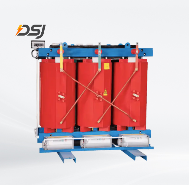
Magnetic Core
The core is typically made from cold-rolled grain-oriented (CRGO) silicon steel laminations. These laminations reduce eddy current losses by limiting the paths through which circulating currents can flow. Core losses (also called no-load losses) in modern dry type transformers are typically between 0.2% and 0.5% of rated capacity, significantly lower than older designs.
Primary and Secondary Windings
Windings are made from copper or aluminum conductors. Copper offers lower resistance and higher current density, while aluminum is lighter and less expensive. In dry type designs, these windings are insulated using one of three main systems:
- Cast Resin (CRT): Windings are encapsulated in epoxy resin, providing excellent moisture and dust resistance. Suitable for Class F (155°C) or Class H (180°C) temperature ratings.
- Vacuum Pressure Impregnation (VPI): Windings are impregnated with polyester or epoxy resin under vacuum, offering good dielectric strength at lower cost than cast resin.
- Open Wound: Traditional design with air as the primary insulation medium, often used for lower-voltage, lower-cost applications.
Enclosure and Cooling System
Dry type transformers use natural air convection (AN) or forced air cooling (AF) via fans. Fan-cooled units can achieve up to 33% additional load capacity compared to the self-cooled rating. Enclosures are rated using NEMA or IP standards — for example, NEMA 3R for outdoor use or IP54 for protected indoor environments.
Thermal Management: How Heat Is Controlled
Heat management is one of the most critical aspects of dry type transformer operation. Unlike oil transformers that use fluid circulation to distribute heat, dry type units rely entirely on their insulation class and airflow design.
The insulation thermal class defines the maximum allowable winding temperature:
| Insulation Class | Max. Temperature | Common Application |
|---|---|---|
| Class B | 130°C | General purpose, light duty |
| Class F | 155°C | Commercial buildings, data centers |
| Class H | 180°C | Heavy industrial, high ambient temps |
| Class C | 220°C+ | Specialized high-temperature environments |
Most modern cast resin dry type transformers are Class F or H, allowing operation in ambient temperatures up to 40°C at altitudes up to 1,000 meters without derating. Above these conditions, the rated capacity must be reduced.
Voltage Regulation and Tap Changers
Dry type transformers are typically equipped with off-circuit tap changers on the primary winding, allowing voltage adjustment in fixed steps — usually ±2.5% and ±5% from the nominal ratio. This compensates for variations in the incoming supply voltage and helps maintain stable output voltage.
Voltage regulation (VR) describes how much the secondary voltage drops from no-load to full-load conditions:
VR (%) = (V_no-load − V_full-load) / V_full-load × 100
Well-designed dry type units achieve a voltage regulation of 2% to 4%, which is adequate for most commercial and industrial loads. Transformers feeding sensitive equipment such as medical devices or precision manufacturing may require tighter regulation through additional voltage stabilization.
Efficiency and Losses
Dry type transformers have two main categories of losses:
- No-load (core) losses: Caused by hysteresis and eddy currents in the magnetic core. These occur continuously whenever the transformer is energized, regardless of load.
- Load (copper) losses: Caused by the resistance of the windings (I²R losses). These increase with the square of the current, so they are much higher at full load than at partial load.
Modern dry type transformers designed to meet international efficiency standards (such as CEATI or IEC 60076-11) achieve efficiencies of 98% to 99.5% at full load for units rated above 300 kVA. At 50% load — a more typical real-world operating point — efficiency can be even higher due to the reduced proportion of load losses.
Dry Type vs. Oil-Filled Transformers: A Practical Comparison
| Feature | Dry Type | Oil-Filled |
|---|---|---|
| Coolant | Air / resin | Mineral or synthetic oil |
| Fire Risk | Low (self-extinguishing resin) | Higher (flammable oil) |
| Maintenance | Minimal (no oil testing) | Regular oil sampling required |
| Installation Location | Indoor, rooftop, substation | Outdoor or dedicated vault |
| Overload Capacity | Moderate | High (oil absorbs more heat) |
| Environmental Risk | None (no fluid leakage) | Spill containment required |
| Typical Voltage Range | Up to 36 kV | Up to 765 kV and beyond |
Typical Applications
Dry type transformers are the preferred choice wherever safety, compactness, or environmental regulations make liquid insulation impractical. Common applications include:
- Commercial buildings: Office towers, hospitals, shopping centers, and hotels where transformers must be located close to electrical load centers on upper floors.
- Data centers: Providing clean, stable power to critical IT infrastructure, where fire risk must be minimized.
- Underground transit: Subway stations and tunnels require transformers with no risk of oil spills or fire propagation.
- Offshore platforms: Marine and oil & gas environments benefit from the sealed, corrosion-resistant construction of cast resin units.
- Renewable energy: Wind turbines and solar plants often use dry type transformers in nacelles or inverter stations due to their compact design and low maintenance needs.
Standard ratings range from as low as 15 kVA for small distribution units to over 30,000 kVA for large industrial applications, with primary voltages typically up to 36 kV.
Monitoring and Protection
Modern dry type transformers are often equipped with embedded temperature sensors (PT100 or PTC thermistors) in the windings to monitor operating temperature continuously. These sensors connect to a temperature controller that provides:
- Alarm signal when winding temperature exceeds a preset threshold (typically 130°C to 155°C depending on insulation class)
- Automatic fan start for forced-air cooling units
- Trip signal to disconnect the transformer if temperature reaches a critical level
Overcurrent protection is provided externally through fuses, circuit breakers, or relay-based protection schemes. Unlike oil-filled transformers, dry type units do not require Buchholz relays or oil level indicators, significantly simplifying the protection system.
Maintenance Considerations
One of the key advantages of dry type transformers is their low maintenance requirement. There is no oil to test, filter, or replace. Routine maintenance typically involves:
- Periodic visual inspection for dust accumulation, especially on cast resin surfaces and cooling ducts
- Cleaning with dry compressed air (never water) to remove dust that could impair cooling airflow
- Checking terminal connections for proper torque and signs of oxidation
- Testing and calibrating temperature monitoring equipment annually
- Verifying fan operation (for AF-cooled units) and replacing fans every 10–15 years as part of planned maintenance
With proper care, a dry type transformer has an expected service life of 25 to 40 years, making it a highly cost-effective solution over its operational lifetime.
For exclusive deals and latest offers, sign up by entering your email address below.



 +86 18513032986
 FLC Center, Chaoyang District, Beijing, China
Copyright © DSJ Electrical Co., Ltd. All Rights Reserved
Power Distribution Equipment & System Manufacturer