Home / News / How to Check a Contactor: A Complete Testing Guide
News

How to Check a Contactor: A Complete Testing Guide

Admin 2026-06-01

Content

Quick Answer

To check a contactor, you need to perform a combination of visual inspection, continuity testing with a multimeter, coil voltage verification, and a live-load operational test. A properly functioning contactor should show infinite resistance (OL) across open contacts and near-zero resistance (0.1–0.5 Ω) across closed contacts. Most contactor failures in switchgear installations come down to worn contact tips, burned coils, or mechanical jamming — all of which are detectable with the right approach.

What Is a Contactor and Why Does It Matter in Switchgear

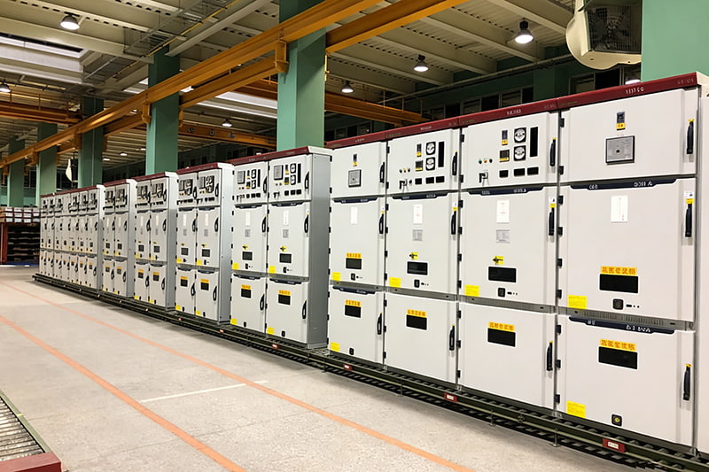
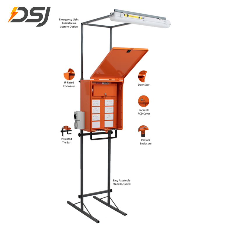
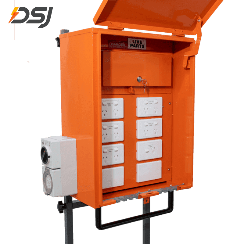
A contactor is an electrically controlled switch used for switching an electrical power circuit. Unlike a standard relay, contactors are designed to handle much higher current loads — commonly from 9A up to 2,500A or more in industrial switchgear assemblies. They are the workhorses inside motor control centers (MCCs), distribution switchgear panels, HVAC units, compressors, and conveyor systems.

In switchgear systems, contactors serve as the interface between the control circuit and the power circuit. When the control coil receives voltage (typically 24V DC, 120V AC, or 240V AC), it generates a magnetic field that pulls in an armature, mechanically closing the main power contacts. When the coil de-energizes, a return spring forces the contacts open.

A failed contactor inside a switchgear enclosure can cause motors to fail to start, create dangerous welded-contact situations where the circuit cannot be opened, or result in intermittent faults that are difficult to trace. Roughly 23% of unplanned industrial downtime is attributed to electrical component failure, and contactors are among the most frequently replaced items in switchgear maintenance programs.

9A–2500A Current range in industrial use
24V–480V Typical coil voltage range
23% Of downtime linked to electrical component failure

Tools and Equipment You Need Before You Start

Before testing any contactor — especially one housed inside a switchgear cabinet — gather the right tools. Attempting tests without proper equipment can yield inaccurate readings or create safety hazards.

M

Digital Multimeter (DMM)

A DMM capable of measuring resistance (Ω), AC/DC voltage, and continuity is essential. Models with auto-ranging (such as Fluke 117 or Klein MM700) save time when switching between resistance and voltage modes. Make sure the meter is rated for at least CAT III 600V when working inside switchgear.

C

Clamp Meter

A clamp meter lets you measure current draw on the load side of the contactor without breaking the circuit. This is useful for confirming that the contactor is passing full rated current once closed. A 400A clamp meter covers the vast majority of smaller switchgear applications.

S

Insulation Resistance Tester (Megohmmeter)

For medium-voltage switchgear contactors or when tracking down insulation breakdown, a megohmmeter (commonly called a Megger) at 500V or 1000V DC test voltage can reveal degraded insulation between poles. A healthy contactor should show insulation resistance above 100 MΩ between open poles.

P

Personal Protective Equipment (PPE)

Arc flash rated gloves (minimum Class 00 for low-voltage work), safety glasses, and appropriate arc flash face protection (arc rating based on incident energy analysis of the switchgear) are non-negotiable. Never perform live tests without verifying the arc flash hazard level of the switchgear panel first.

Step-by-Step Visual Inspection of a Contactor

Visual inspection should always be the first step. Many contactor problems announce themselves clearly if you know what to look for. This process applies whether the contactor is mounted in a standalone motor starter or inside a complex switchgear assembly.

01

De-energize and Lock Out / Tag Out (LOTO)

Before opening any switchgear panel, follow your facility's LOTO procedure. Isolate all upstream power sources, apply lockout devices to all disconnect points, and use a voltage tester to confirm zero energy state at the contactor terminals. This step is not optional — switchgear cabinets can contain multiple voltage sources including control transformers, CPT taps, and bus sections that remain energized even when the main breaker is open.

02

Inspect the Contact Tips

With the contactor de-energized, manually depress the armature to close the contacts and inspect the tips. New contact tips are typically silvery and flat. Worn contacts appear pitted, blackened, or severely eroded. When contact tip material has worn away by more than 50% of the original thickness, the contactor must be replaced — attempting to clean heavily worn contacts only delays failure. On three-phase contactors, check all three poles; uneven wear between poles indicates a load imbalance problem upstream.

03

Check for Burning, Tracking, and Carbon Deposits

Look for black carbon tracks on the contact bridge or the contact carrier. Carbon tracking indicates arcing has been occurring — this can result from repeated switching under load, contact bounce, or insufficient contact pressure. Light carbon can sometimes be cleaned with a dry cloth; heavy tracking usually means the contact block or entire contactor needs replacement. Never use sandpaper or files on silver-alloy contacts — this removes the plating and dramatically accelerates wear.

04

Examine the Coil and Coil Housing

The coil sits in the lower half of the contactor and pulls the armature when energized. A burned coil often has a distinct acrid smell and may show visible discoloration of the bobbin or varnish. Check coil lead wires for fraying or heat damage at the terminals. On DC-operated coils, check whether the arc suppression diode or resistor (if present) shows signs of overheating — these components protect the control circuit from back-EMF spikes and fail more often than many technicians realize.

05

Inspect the Mechanical Components

Check the armature for smooth movement — it should travel freely with no binding when you manually press and release it. Check return springs for deformation or corrosion. On contactors used in outdoor switchgear or harsh environments, corrosion of the armature shading ring (the copper or aluminum ring embedded in the armature face) can cause the contactor to buzz loudly and eventually fail to hold in. A damaged shading ring is not field-repairable and requires full contactor replacement.

How to Test a Contactor with a Multimeter

A digital multimeter is the primary diagnostic instrument for contactor testing. The tests below cover the three main checks: contact continuity, coil resistance, and coil voltage. Perform these in order for a complete picture of the contactor's condition.

Test 1 — Contact Continuity (Power Contacts)

Set your multimeter to the continuity or resistance (Ω) mode. With the contactor de-energized and contacts open:

  • Place probes across the Line (L) and Load (T) terminals of each pole.
  • The meter should read OL (open loop / infinite resistance) — if it reads continuity or low resistance with contacts open, the contacts are welded closed. This is a critical fault.
  • Manually depress the armature to close the contacts. Now the meter should read near zero — typically 0.1 to 0.5 Ω on healthy contacts.
  • Repeat for all three poles on a three-phase contactor.
  • If one pole reads significantly higher (e.g., 2 Ω or more while others read 0.2 Ω), that pole has excessive resistance from worn or oxidized contacts.

Test 2 — Auxiliary Contact Continuity

Auxiliary contacts (typically labeled NO/NC — Normally Open / Normally Closed) are used in control circuits for feedback, interlocking, and signaling within switchgear control systems.

  • With the contactor de-energized: NC auxiliary contacts should show continuity (near-zero Ω); NO contacts should show OL.
  • With the armature manually depressed: NO contacts should close (near-zero Ω); NC contacts should open (OL).
  • Auxiliary contacts that fail to switch properly cause phantom faults in PLC control logic — a contactor may operate correctly in the power circuit but falsely report a fault to the control system due to a bad auxiliary contact.

Test 3 — Coil Resistance

Set your multimeter to resistance mode and connect probes to the two coil terminals (labeled A1 and A2 on most contactors). Compare your reading against the manufacturer's specification:

Contactor Size / Coil Voltage Typical Coil Resistance Fault Indication
Small (9–25A), 24V DC coil 20–80 Ω OL = open winding; <5 Ω = shorted turns
Medium (40–95A), 120V AC coil 200–800 Ω OL = open winding; unusually low Ω = shorted coil
Large (150–400A), 240V AC coil 1,000–5,000 Ω OL = burned open; significant deviation = suspect
Large (150–400A), 480V AC coil 4,000–20,000 Ω OL = burned open; significant deviation = suspect
Typical contactor coil resistance values by size and voltage — always verify against the specific manufacturer's datasheet

Test 4 — Coil Voltage (Live Test)

With power restored and the control circuit energized (follow all PPE and safe work practice requirements):

  • Set your multimeter to the appropriate AC or DC voltage range.
  • Measure voltage across terminals A1 and A2 when a start command is issued.
  • The reading should be within ±10% of the rated coil voltage. A 120V AC coil should see between 108V and 132V to operate reliably.
  • Voltage present at the coil but the contactor failing to pull in = mechanical fault or open coil winding.
  • No voltage at the coil = control circuit fault upstream of the contactor (blown fuse, bad overload relay, failed PLC output, etc.).

Common Contactor Failure Modes and What Causes Them

Understanding why contactors fail helps you both diagnose existing problems and prevent future ones. In switchgear maintenance programs, these failure modes appear most often:

Welded Contacts

Contacts weld together when an excessive inrush current causes the contact tips to momentarily melt and fuse. This is common when contactors are not rated for the full motor inrush current (typically 6–8× full load amps on direct-on-line starts). A welded-contact condition creates a dangerous situation because the circuit cannot be opened through the control system — only physically breaking the upstream switchgear will de-energize the load.

Contact Erosion and High Resistance

Every switching operation removes a small amount of contact material. A contactor rated for 1 million operations at full load may only last 100,000 operations if consistently switching above its rated current. High-resistance contacts cause localized heating, which accelerates further wear. A contact drop of more than 50mV at rated current is generally considered excessive and indicates replacement is needed.

Coil Burnout

Coil burnout typically results from sustained overvoltage, excessive ambient temperature inside the switchgear cabinet, or the armature mechanically failing to fully seat (creating a condition called shading — the gap in the magnetic circuit causes the coil to draw higher than rated current continuously). Control voltage that consistently runs 15–20% above the rated coil voltage will shorten coil life dramatically.

Chattering and Humming

A contactor that chatters (rapidly opening and closing) or hums loudly usually has a control voltage problem — voltage dipping below the drop-out threshold during operation — or a damaged shading ring on the armature face. Chattering causes extreme contact wear in a short period. Each chattering event subjects the contacts to thousands of micro-arcing events per second, destroying the contact surface far faster than normal switching.

Mechanical Jamming

Foreign material (dust, debris, insect nests in outdoor switchgear), swollen return springs, or deformed plastic carrier parts can prevent the contacts from opening or closing fully. Partial contact closure creates a high-resistance connection that generates heat. Mechanical jamming is especially common in contactors that sit unused for extended periods in humid or dusty environments.

Insulation Failure Between Poles

In high-voltage switchgear or in environments with conductive contamination (carbon dust, conductive coolants), insulation between the three power poles can break down. This creates phase-to-phase arcing inside the contactor itself, which is often a catastrophic failure. Regular insulation resistance testing (Megger testing) as part of a preventive maintenance schedule catches this before it becomes a fault.

Performing a Live Operational Test on a Contactor

Once static tests (de-energized checks) pass, a live operational test confirms the contactor performs correctly under actual working conditions. This is the definitive test for switchgear contactors before returning equipment to service.

  1. Restore control power only — do not re-apply load power yet. Energize the coil circuit and confirm the contactor pulls in cleanly without chattering or buzzing. Observe whether all three poles close simultaneously.
  2. Verify auxiliary contact switching — with a helper or using your control system display, confirm that NO and NC auxiliary contacts switch state when the contactor energizes and de-energizes.
  3. Restore load power — energize the contactor under load conditions. Use a clamp meter on each of the three phases to verify balanced current draw. For a motor load, current should be within 5–10% of nameplate full load amps at full speed.
  4. Perform multiple switching cycles — cycle the contactor on and off 5–10 times while monitoring for unusual sounds, heat buildup, or sparking. The contactor should respond consistently each time without delay or hesitation.
  5. Check contact temperature under load — using an infrared thermometer or thermal camera, check the contactor's power terminals and contact area after 15–30 minutes of operation. Temperature rise at the terminals should not exceed 40°C above ambient for a healthy contactor. Higher temperature indicates elevated contact resistance.

Preventive Maintenance Best Practices for Contactors in Switchgear

Reactive replacement after failure is more costly than a structured maintenance program. The following practices are used in professional switchgear maintenance to extend contactor service life and prevent unexpected failures.

Establish Inspection Intervals Based on Switching Frequency

A contactor switching a motor that starts twice per day accumulates roughly 730 operations per year — far less demanding than one on a conveyor that starts 50 times per shift. Establish inspection intervals based on actual operation count where possible. IEC 60947-4-1 and NEMA ICS 2 standards provide guidance on contact wear limits and maintenance intervals relative to operational class.

Keep a Contact Wear Measurement Log

On larger contactors (typically above 100A), it is practical to measure contact tip thickness at each inspection. Record these measurements over time. When the contacts reach the manufacturer's minimum thickness specification — typically stamped on the contact block or listed in the maintenance manual — schedule replacement before failure occurs rather than after.

Control Cabinet Climate Management

Switchgear cabinets with high ambient temperatures dramatically shorten contactor coil life. A rule of thumb used in industrial maintenance is that every 10°C increase in operating temperature halves the insulation life of the coil winding. Verify cabinet ventilation, clean air filters on forced-ventilation switchgear, and check thermostat settings on cabinet heaters (used in cold climates to prevent condensation).

Verify Control Voltage Stability

Control voltage that sags below the dropout voltage of the contactor during large motor starts is a common but often overlooked problem in switchgear installations. Use a recording voltmeter or data logger on the control voltage bus during start events. If voltage dips below 85% of rated coil voltage for more than 50–100ms during starts, the contactor may intermittently chatter, accelerating wear dramatically.

Stock Critical Spare Parts

For critical switchgear applications — pump stations, compressors, production equipment — maintain at least one spare contactor of each type in the facility's spare parts inventory. When a contactor fails and the replacement must be ordered and shipped, downtime can extend to days. The cost of a spare contactor (often $50–$500 for standard sizes) is insignificant compared to the cost of extended downtime.

When to Repair vs. Replace a Contactor

The decision to repair or replace is primarily economic and safety-driven. Here is a practical framework used in switchgear maintenance programs:

Condition Found Repair or Replace Notes
Light carbon on contacts, tips within wear limit Clean and return to service Use dry cloth only — no abrasives
Contact tips worn beyond 50% of original thickness Replace contact block or full contactor Contact blocks are replaceable on many larger contactors
Welded contacts Replace full contactor Also investigate root cause of welding
Burned or open coil Replace coil or full contactor Replacement coils available for most standard contactors
Damaged shading ring Replace full contactor Not a field-repairable component
Cracked or broken housing/carrier Replace full contactor Structural integrity compromised — safety risk
High inter-pole insulation resistance failure Replace full contactor Cannot be safely repaired in field
Repair vs. replace decision framework for contactors in switchgear maintenance

Frequently Asked Questions About Checking Contactors

Can I test a contactor without removing it from the switchgear panel?

Yes, for most tests. Coil resistance, coil voltage, and auxiliary contact checks can usually be performed in place. Power contact continuity testing while manually depressing the armature is also feasible in place, though access may be limited in densely packed switchgear assemblies. For thorough contact inspection and measurement, removal is recommended.

What does it mean if my contactor pulls in but immediately drops out?

This usually indicates that control voltage is marginal — just enough to pull in the contactor but dropping below the hold-in voltage threshold immediately afterward. It can also indicate a mechanical issue where the armature is not seating fully, causing the magnetic circuit to be inefficient. Check control voltage under load and verify the armature moves freely with no binding.

How do I know what coil voltage my contactor uses?

The coil voltage is typically printed on a label on the side of the contactor, or embossed on the coil housing itself. In switchgear installations, it is also documented in the panel's wiring diagram or one-line diagram. Common voltages are 24V DC, 120V AC, 240V AC, and 480V AC. Never assume — applying the wrong coil voltage will burn the coil immediately or prevent operation.

Is there a way to test a contactor without a multimeter?

A basic functional test is possible without a multimeter: manually depress the armature and listen/feel for smooth mechanical operation; energize the coil and confirm the contactor pulls in cleanly with a clear snap; check visually for burning, pitting, or obvious damage. However, this approach misses quantitative data — coil resistance, contact resistance, and voltage levels all require a meter. For any contactor going back into service in switchgear, meter-based testing is the professional standard.

How often should contactors in switchgear be inspected?

NEMA ICS 2 and IEC 60947 standards recommend inspection intervals based on operational class and switching frequency. A general rule for industrial switchgear in moderate-duty applications is annual visual inspection with multimeter testing every 1–3 years, or after any known fault event (short circuit, overload trip, or voltage transient). High-cycle applications (contactors switching more than 10 times per hour) warrant more frequent attention — some facilities inspect every 6 months or track cumulative operation counts.