+86 18513032986


How to Check an AC Contactor: Full Testing Guide
Admin 2026-06-22Content
- 1 What an AC Contactor Actually Does Inside Your System
- 2 Tools and Safety Gear You Need Before You Start
- 3 Step-by-Step Visual Inspection: What to Look For and What It Means
- 4 Electrical Testing with a Multimeter: Coil, Contacts, and Insulation
- 5 Common AC Contactor Faults, Root Causes, and How to Diagnose Them
- 6 Testing Contactors Inside Switchgear Panels and Motor Control Centers
- 7 Checking AC Contactors in HVAC Condensing Units: Field Procedure
- 8 When to Repair vs. When to Replace an AC Contactor
- 9 Recommended Inspection and Maintenance Schedule for AC Contactors
- 10 Frequently Asked Questions About Checking AC Contactors
Checking an AC contactor comes down to four core steps: a visual inspection for burn marks or pitting, a coil continuity test with a multimeter, a contact resistance check, and an operational load test under power. Most failures are caught within the first two steps. Whether you are troubleshooting a rooftop HVAC unit, a motor control center, or a larger switchgear panel, the workflow is the same — you just need the right meter reading and a clear understanding of what the numbers mean.
What an AC Contactor Actually Does Inside Your System
An AC contactor is an electrically operated switch designed to carry and interrupt high-current circuits. Unlike a standard relay, contactors are built for heavier loads — typically anything from 9 amps up to several thousand amps in large industrial switchgear assemblies. The contactor sits between your power supply and the load (a motor, compressor, lighting bank, or heating element) and opens or closes that circuit in response to a low-voltage control signal sent to its coil.
When the control coil is energized, an electromagnetic field pulls the movable armature downward (or in some designs, laterally), pressing the moving contacts against the stationary contacts and completing the main circuit. When the coil de-energizes, a return spring pushes the armature back and the contacts separate, breaking the load circuit. The speed and consistency of this mechanical action is what determines contactor lifespan. A well-maintained contactor rated for 1,000,000 operations can last fifteen or more years; a neglected one with pitted contacts may fail within eighteen months.
Inside a typical switchgear cabinet, you may find anywhere from a single contactor controlling one motor to a bank of a dozen or more arranged in star-delta starters, reversing circuits, or multi-speed motor configurations. Understanding the role of each contactor in that arrangement is essential before you begin testing — knowing whether you are looking at a main contactor, a star contactor, or an auxiliary contactor changes both what you are testing and what a pass/fail result means for the system.
Tools and Safety Gear You Need Before You Start
Digital Multimeter (CAT III or CAT IV)
A CAT III-rated meter (minimum 600 V) handles most HVAC and light industrial contactors. For work inside switchgear panels operating above 1,000 V, use a CAT IV meter. Set the meter to resistance (Ohms) for coil and contact tests, and to AC voltage for operational tests.
Clamp Meter
Used during the live operational test to verify actual load current drawn through each pole. Compare the reading against the contactor's rated current and the connected motor's nameplate FLA (Full Load Amperage). Readings more than 10% above nameplate indicate a potential problem upstream.
Insulation Resistance Tester (Megohmmeter)
Used at 500 V DC on 240/480 V systems and at 1,000 V DC on 600 V systems. Measures insulation integrity between poles and between poles and the contactor frame. Readings below 1 MΩ indicate compromised insulation requiring immediate attention.
Contact Resistance Meter (Micro-ohmmeter)
For precision testing in critical switchgear applications. Measures contact resistance in micro-ohms. New silver-alloy contacts typically read below 100 μΩ. Contacts exceeding 300 μΩ are approaching the end of useful life and should be flagged for replacement at the next scheduled outage.
PPE: Arc Flash and Shock Protection
At minimum, wear voltage-rated gloves (Class 00 for up to 500 V), safety glasses, and arc-flash face shield rated to the incident energy level of the panel. Never work on energized switchgear without completing an arc flash hazard assessment first.
Lockout/Tagout (LOTO) Equipment
Padlock, hasp, and lockout tags. Any off-power testing — coil resistance, contact resistance, insulation — requires positive lockout of all energy sources. Never rely on contactor position alone as proof of de-energization.
Step-by-Step Visual Inspection: What to Look For and What It Means
Visual inspection is the fastest and most informative first step. Always perform it with the system locked out and the contactor fully de-energized. Remove the contactor from the panel or switchgear enclosure if it is plug-in type; for fixed-mount types, open the enclosure and work in place.
Main Contacts: Surface Condition
Silver-cadmium oxide or silver-tin oxide contacts are designed to develop a black oxidation layer in service. This oxide layer is electrically conductive and is normal — do not file or sand it off. What you are looking for instead is physical damage:
- Deep pitting or craters: indicates repeated arcing, often from high inductive load switching or from contacts closing too slowly due to a weak coil
- Material transfer (one contact face has a lump, the opposite has a corresponding depression): common on DC switching or unbalanced AC phases, causes hot spots and uneven contact pressure
- Contact material worn through to base copper: the contact appears bright copper-orange rather than dark grey. Remaining contact life is near zero
- Melted or fused contacts: indicates a short circuit or sustained overload event that the contactor was not rated to interrupt
As a general guideline, replace contacts when the contact material thickness has worn to 50% of original. Most manufacturers provide a wear indicator groove or a minimum thickness specification in the contactor's datasheet — consult the specific document for your model.
Coil and Magnet Assembly
Examine the coil body for discoloration (brown or black indicates overheating), cracking of the insulation varnish, or a burnt odor. Check the shading ring on the magnet pole face — this small copper ring prevents chatter on AC contactors. A broken shading ring causes a loud humming or chattering sound during operation and rapid armature wear. Visually inspect the magnet pole faces for rust or contamination, which increases the air gap and causes the coil to draw higher current to close, accelerating coil burnout.
Arc Chutes and Arc Runners
Arc chutes are the ribbed or baffle-type insulating structures that surround the contacts. They quench and cool the arc produced each time contacts open under load. Inspect them for:
- Heavy carbon tracking or carbonization: reduces insulating ability and can cause phase-to-phase faults in multi-pole contactors
- Cracked or shattered arc chute plates: common after severe fault-current interruptions; must be replaced, not cleaned
- Metallic debris from contact erosion: clean with dry compressed air (never with solvents that could contaminate silver contacts)
Mechanical Components: Springs, Pins, and Bushings
Check the return spring for deformation or corrosion. A weak return spring causes contacts to open slowly, increasing arcing and contact erosion. Inspect pivot pins and bushing bores for wear — excessive play in the armature pivot causes misalignment and uneven contact pressure across the three poles, leading to one pole carrying disproportionate current.
Terminal Connections and Wiring
Loose or corroded terminals are among the most common causes of contactor overheating. Use a thermal imaging camera if available; a loose terminal creates a high-resistance joint that generates significant heat at load current. Visually, look for discoloration of the terminal insulation, melted plastic around terminal screws, or greenish corrosion on copper conductors. Retighten terminals to manufacturer torque specifications — under-torqued terminals vibrate loose over time, especially in environments with mechanical vibration.
Electrical Testing with a Multimeter: Coil, Contacts, and Insulation
Coil Resistance Test (De-energized)
With the contactor isolated and locked out, disconnect the coil control wires and measure resistance across the coil terminals. The expected reading depends on the coil voltage rating and design. As a general guide:
| Coil Voltage Rating | Typical Resistance Range | Reading Indicating Fault |
|---|---|---|
| 24 V AC | 5 – 20 Ohms | OL (open) = broken winding; 0 Ohms = shorted winding |
| 120 V AC | 200 – 800 Ohms | OL = broken winding; very low = inter-turn short |
| 240 V AC | 500 – 2,000 Ohms | OL = broken winding; very low = inter-turn short |
| 480 V AC | 1,500 – 6,000 Ohms | OL = broken winding; very low = inter-turn short |
A reading of OL (overload/open circuit) on the resistance scale means the coil winding is broken — replace the coil or the entire contactor. A reading of zero or near-zero ohms indicates a shorted coil that will blow the control fuse when energized. A reading significantly lower than the datasheet specification (but not zero) suggests partial inter-turn shorting, which causes overheating of the coil and eventual failure.
Contact Continuity and Resistance Test (De-energized)
This test checks two conditions: that contacts are open when de-energized (normally open contacts should read OL), and that they close properly when actuated.
For the open-state test: with the contactor de-energized, place meter leads across each pair of main contacts (L1 to T1, L2 to T2, L3 to T3). The multimeter should read OL on all three poles. Any reading other than OL indicates welded or sticking contacts — a serious fault that prevents the load from being safely de-energized.
For the closed-state test: press the contactor plunger manually (after verifying the circuit is de-energized and locked out) and measure resistance across each set of contacts with the contacts held closed. Healthy silver-alloy contacts should read below 0.5 Ohms on a standard multimeter. Higher readings indicate excessive contact resistance from oxidation, pitting, or inadequate spring pressure.
Insulation Resistance Test Between Poles
With the contactor de-energized and isolated, close the contacts manually and apply the megohmmeter between each phase pair (L1 to L2, L2 to L3, L1 to L3) and between each phase and the contactor frame (earth). A healthy contactor should return readings above 100 MΩ on a new unit. For in-service testing, readings above 10 MΩ are generally acceptable; readings between 1 MΩ and 10 MΩ warrant further investigation and increased monitoring frequency. Below 1 MΩ requires immediate action.
Operational (Energized) Test
After satisfactory off-power test results, restore power and observe the contactor operating under normal control conditions. Use a clamp meter on each phase conductor to verify balanced current draw. Listen for:
- Chattering or humming: indicates a broken shading ring, low control voltage, or a contaminated magnet face
- Delayed closing: the contactor pulls in slowly, suggesting a weak coil, low control voltage, or a sticking armature
- Sparking visible from arc chute area: normal during opening under full load, but persistent sparking during closing suggests contact bounce, indicating worn contacts or weak contact pressure springs
Measure the control voltage at the coil terminals during the energized test. The coil must receive a voltage within its specified operating range — typically 85% to 110% of the rated coil voltage. Low control voltage is the most common cause of coil overheating and premature failure because the coil draws higher current trying to pull in the armature against a reduced magnetic force.
Common AC Contactor Faults, Root Causes, and How to Diagnose Them
The table below summarizes the most frequently encountered contactor faults across residential HVAC systems, light commercial equipment, and industrial switchgear installations. Root cause identification is the key to preventing the same failure from recurring after replacement.
| Symptom | Test Result | Likely Root Cause | Action |
|---|---|---|---|
| Load will not start, coil energizes | High resistance or OL across closed contacts | Welded-open or heavily pitted contacts | Replace contacts or full contactor |
| Load will not shut off | Contacts read continuity when de-energized | Welded contacts from fault current or inrush | Replace contactor; investigate upstream fault |
| Loud chattering during operation | Visual: broken shading ring; control voltage low | Shading ring fracture or under-voltage | Replace contactor or correct control voltage |
| Coil blows control fuse repeatedly | Coil resistance = 0 Ohms or very low | Shorted coil winding | Replace coil or full contactor |
| One phase shows high current, others normal | High contact resistance on one pole only | Uneven contact wear or weak contact spring | Replace contacts and check spring pressure |
| Insulation failure between phases | Megohmmeter reads below 1 MΩ phase-to-phase | Carbon tracking in arc chutes or contamination | Replace arc chutes; full inspection |
Testing Contactors Inside Switchgear Panels and Motor Control Centers
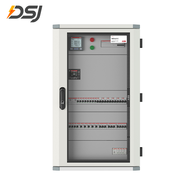
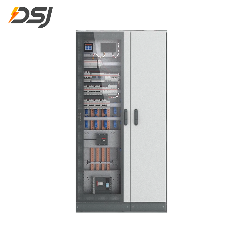
When a contactor is mounted inside a switchgear panel or motor control center (MCC), the testing approach needs to account for the surrounding equipment and the higher energy levels present. Industrial switchgear assemblies often contain multiple contactors, fuses, overload relays, control transformers, and metering equipment in a single enclosure. Disturbing one component can affect others, and the consequences of errors are more severe.
Isolation Procedures in Switchgear Environments
Before testing any contactor inside a switchgear assembly, the relevant section must be de-energized through the upstream isolator or circuit breaker and locked out. In draw-out style MCC buckets, the entire starter bucket can be racked out to the "test" or "disconnected" position, physically separating the line-side stabs from the bus. This is the preferred approach for testing because it removes all upstream hazard energy from the bucket while allowing the control circuit to remain energized for coil tests.
For fixed-mount switchgear, de-energize the section, verify absence of voltage on all phases with a voltage detector, then apply LOTO before opening the panel door. Work within the restricted approach boundary using appropriate PPE rated to the incident energy level of the specific switchgear section.
Testing Contactors as Part of a Broader Switchgear Maintenance Program
In a comprehensive switchgear maintenance program, contactor testing is typically carried out alongside overload relay calibration, bus bar torque verification, insulation resistance testing of cables and bus, and functional testing of protection relays. The interval varies by application. For medium-voltage switchgear operating in harsh industrial environments, manufacturers including ABB, Schneider Electric, and Siemens recommend annual maintenance intervals. For low-voltage switchgear in clean, climate-controlled facilities, biennial or triennial intervals are common, supplemented by thermal imaging scans conducted annually without opening panels.
Thermal imaging (infrared thermography) is particularly effective for identifying failing contactors in switchgear without interrupting production. A contactor with high contact resistance will show elevated temperature on its line and load terminals compared to adjacent contactors carrying similar loads. According to the NFPA 70B Recommended Practice for Electrical Equipment Maintenance, thermal anomalies more than 15°C above the baseline of similar equipment under similar load should trigger further investigation and corrective action.
Overload Relay Coordination During Contactor Testing
In most motor starter circuits within switchgear, the contactor operates in series with a thermal or electronic overload relay. When testing the contactor operationally, verify that the overload relay is not tripped before concluding that the contactor itself is the fault. An overload relay that has tripped looks exactly like a failed contactor from a system-level perspective — the motor does not start. Reset the overload relay and observe whether it trips again under load; if so, the problem is the motor or the overload setting, not the contactor.
Also verify overload relay continuity during the de-energized contactor test. Some electronic overload relays have an auxiliary contact that must be in the closed position for the contactor coil control circuit to be complete. A tripped or faulty overload relay auxiliary contact will prevent the coil from energizing even if the coil itself is healthy.
Testing Auxiliary Contacts and Interlocks
Many contactors carry auxiliary contact blocks — small supplementary contacts that switch at the same time as the main contacts. These are used in switchgear control circuits for indicator lights, permissive interlocks, and PLC feedback signals. Test auxiliary contacts with the multimeter in the same way as main contacts: OL when open, near-zero resistance when closed. Auxiliary contacts are typically lighter-duty and wear faster than main contacts if they carry inductive loads or are switched at high frequency. In reversing switchgear starters, the normally closed (NC) auxiliary contacts of each contactor provide the electrical interlock that prevents both contactors from closing simultaneously — if these contacts fail, the system loses its electrical interlock and a phase-to-phase fault becomes possible. Verify these interlocks carefully during any contactor maintenance on reversing starters.
Checking AC Contactors in HVAC Condensing Units: Field Procedure
Residential and light commercial HVAC condensing units use single-pole or double-pole contactors rated typically between 20 A and 60 A at 240 V AC. The contactor switches power to the compressor and the condenser fan motor in response to a 24 V AC control signal from the thermostat. Because these units cycle frequently — potentially thousands of times per season — contactors in HVAC applications are among the most actively stressed contactors in common use.
Disconnect Power and Confirm Absence of Voltage
Pull the disconnect block or breaker at the unit's disconnect box and verify with a non-contact voltage tester or multimeter that voltage is absent at the line side of the contactor. The unit also has 24 V AC control voltage from the thermostat — this will be present even with the main disconnect pulled unless the thermostat circuit is separately interrupted.
Visually Inspect Contact Surfaces
Remove the wiring cover and examine the contact faces. Pitted, burned, or stuck contacts are extremely common in HVAC contactors exposed to years of cycling, insect nesting (ants are notorious for nesting inside contactors and causing them to weld), and moisture ingress. If you see any of the following, replace the contactor: contact faces worn to bare copper, obvious welding or fusing, ant or insect contamination in the contact area, or heavy pitting across more than 30% of the contact face area.
Measure Coil Resistance
Disconnect the 24 V control wires from the coil terminals and measure resistance. A 24 V AC HVAC contactor coil typically reads between 8 Ohms and 20 Ohms, depending on manufacturer and amperage rating. An OL reading confirms an open coil — the contactor cannot pull in. A zero reading confirms a shorted coil — it will blow the 24 V control fuse or damage the transformer.
Check Contact Resistance Manually
With the power disconnected, manually depress the contactor plunger (the plastic button or bridge visible on top of the contactor body) and measure resistance across L1-T1 and L2-T2. Both should read well below 1 Ohm — ideally under 0.5 Ohms. A reading above 1 Ohm with the contacts manually held closed indicates the contacts are pitted or corroded beyond acceptable service limits.
Restore Power and Check Control Voltage
Restore power and call for cooling at the thermostat. With the unit running, measure AC voltage at the contactor coil terminals — you should read approximately 24 V AC (typically 23 V to 27 V is acceptable). Check line voltage at the line side of the contactor and load voltage at the load side. If line voltage is present but load voltage is absent and the coil is energized, the contacts are the problem. If line voltage is present and load voltage matches line voltage but the compressor does not run, the problem is downstream of the contactor.
When to Repair vs. When to Replace an AC Contactor
Contact kits (replacement contacts and springs) are available for many industrial contactors as a lower-cost alternative to full replacement. The decision between contact replacement and full contactor replacement depends on the condition of the remaining components and the economics of the situation.
- Contact faces worn but coil, arc chutes, and mechanical components in good condition
- Large or medium industrial contactors where full unit cost is high (typically above $500 replacement cost)
- Contact kit available from the original manufacturer and within a reasonable delivery lead time
- Contactor frame and housing free of cracks, deformation, or contamination
- Switchgear integration where a full contactor swap requires significant rewiring or bus modifications
- Coil is shorted or open — coil replacement is available but the total labor cost often approaches full unit price for small contactors
- Arc chutes cracked or destroyed by fault current
- Mechanical pivot or bushing wear causing armature misalignment
- Small HVAC contactors (under $30–$60 typical replacement cost) — economically unjustifiable to attempt repair
- Contact welding or fusing indicates the contactor was exposed to fault levels beyond its rating — the frame may be mechanically compromised
- Age — contactors in service beyond 15 years or beyond the manufacturer's recommended service life should be replaced wholesale during any maintenance outage regardless of apparent condition
When ordering a replacement contactor, always match the following specification parameters to the original: frame size / current rating (amperes), utilization category (AC-1, AC-2, AC-3, AC-4 etc.), number of poles, coil voltage and frequency, and auxiliary contact configuration. Substituting a contactor with a higher current rating is generally acceptable; substituting a lower rating is not. In switchgear applications, also confirm that the replacement contactor's physical dimensions and mounting bolt pattern match the enclosure — different manufacturers' products of the same ampere rating often have different footprints.
Recommended Inspection and Maintenance Schedule for AC Contactors
A structured maintenance schedule based on application and environmental conditions prevents unplanned failures. The intervals below are starting points — adjust based on your specific operating cycle count, ambient conditions, and any unusual events (voltage surges, fault currents, extreme temperatures).
| Application | Inspection Interval | Full Electrical Test Interval | Notes |
|---|---|---|---|
| Residential HVAC | Annual (spring tune-up) | Every 5 years or on symptom | Replace proactively at 7–10 years |
| Light commercial HVAC / refrigeration | Semi-annual | Annual | Thermal imaging recommended |
| Industrial motor control (light duty) | Annual | Annual | Per NEMA ICS 1.3 |
| Industrial motor control (heavy / AC-4 duty) | Quarterly or per cycle count | Semi-annual | Monitor operation count against rated life |
| Low-voltage switchgear (indoor, clean) | Annual thermal scan | Every 3 years | Per manufacturer PM recommendations |
| Low-voltage switchgear (outdoor / harsh) | Semi-annual thermal scan | Annual | Check seals and desiccant packs |
Frequently Asked Questions About Checking AC Contactors
For exclusive deals and latest offers, sign up by entering your email address below.




 +86 18513032986
 FLC Center, Chaoyang District, Beijing, China
Copyright © DSJ Electrical Co., Ltd. All Rights Reserved
Power Distribution Equipment & System Manufacturer